方案 · 域控制器Solution · Zone Controller

VCU 整车控制器VCU Vehicle Controller硬件方案Hardware Design

把整车意图,翻译成三电与车身的指令Translating driver intent into commands

VCU 是整车电控的决策中枢:采集驾驶意图与车辆状态,判断运行模式,再向动力、制动、车身各子系统下发指令。它同时常驻网关职能,是不同 CAN 域之间数据流转的枢纽。本文给出一套以 NXP TJA1044T 双通道高速 CAN 收发器为核心的 VCU 硬件方案:为什么是四路 CAN 分层、这颗收发器解决了什么、完整电路设计要盯哪些点。The VCU is the decision hub of the vehicle's electronic control system: it reads driver intent and vehicle state, decides the operating mode, then commands the powertrain, braking and body subsystems. It also permanently hosts gateway duties, acting as the junction where data crosses between CAN domains. This piece presents a VCU hardware design built around the NXP TJA1044T dual-channel HS-CAN transceiver: why four CAN channels, what this transceiver solves, and what to watch in the full circuit design.

Architecture

VCU 在整车网络中的位置Where the VCU sits in the vehicle network

VCU 不是"某个ECU",而是整车控制决策层——它不在子系统里平等地当一个节点,而是位于子系统之上,决定它们协同做什么。The VCU is not "one ECU among equals" — it is the supervisory decision layer, sitting above the subsystems and deciding what they do together.
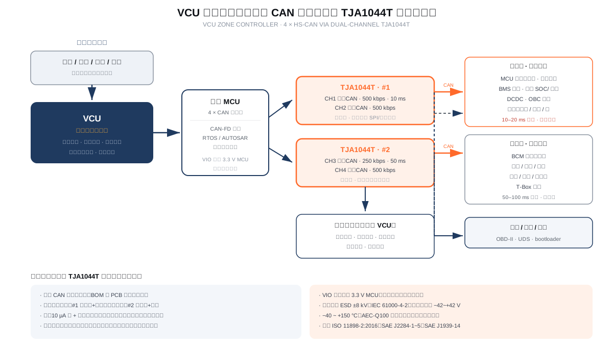
VCU 整车控制器四路 CAN 分层架构与 TJA1044T 收发器布置框图
为什么整车要分网,而不是一根 CAN 走天下Why segment the network instead of one CAN bus 不同子系统的实时性要求差着数量级。动力系统的扭矩指令周期可能只有 10 ms甚至 5 ms,延迟几毫秒就影响驾驶安全;而车身控制里车窗升降、灯光状态的周期 100 ms 都不为过。全部混在一根总线上,低速报文会占满带宽,高速报文等不到总线空闲,实时性直接崩掉。分网还带来故障隔离:车身 CAN 因为某个车窗电机短路而总线错误时,动力 CAN 仍能正常工作,车辆至少保住动力输出与制动安全——这正是 ISO 26262 对安全相关系统要求独立通信路径的底层逻辑。常见分法是:动力 CAN(VCU / MCU / BMS / DCDC / OBC,500 kbps 高优先级)、车身 CAN(BCM / 门窗 / 灯光 / 座椅,125–250 kbps)、诊断 CAN(OBD / 刷写 / 标定,500 kbps)、底盘 CAN(ESP / EPB / 转向,安全相关)。 Real-time requirements differ by orders of magnitude. A powertrain torque command period can be 10 ms or even 5 ms — a few milliseconds of latency affects driving safety, while a window or light status cycle of 100 ms is perfectly fine. On a single mixed bus, low-rate traffic eats the bandwidth and high-rate messages starve waiting for idle time; real-time behaviour collapses. Segmentation also buys fault isolation: if a window motor short causes bus errors on body CAN, powertrain CAN keeps working and the vehicle retains drive and braking safety — exactly the logic behind ISO 26262's requirement for independent communication paths in safety-related systems. The typical split is Powertrain CAN (VCU / MCU / BMS / DCDC / OBC, 500 kbps, high priority), Body CAN (BCM / doors / lights / seats, 125–250 kbps), Diagnostic CAN (OBD / flashing / calibration, 500 kbps) and Chassis CAN (ESP / EPB / steering, safety-related).
职责 ①Role 1

驾驶意图 → 扭矩需求Driver intent to torque demand

采集油门踏板、挡位、制动踏板判断驾驶意图,结合车速、温度、电池 SOC 算出扭矩需求与能量分配,再生制动与驱动如何混合也在这里决定。VCU 不直接控制电机,而是把扭矩指令发给 MCU,由逆变器执行——MCU 会把实际扭矩、转速、温度回传上来。Read accelerator, gear and brake to interpret driver intent; combine with vehicle speed, temperature and battery SOC to compute torque demand and energy distribution, including how regen and drive blend. The VCU does not drive the motor directly — it sends torque commands to the MCU, and the inverter reports actual torque, speed and temperature back.

职责 ②Role 2

限值约束与安全状态Limits and safe state

BMS 上报的 SOC、可用充放电功率、电池温度是硬约束,VCU 的扭矩请求不能越过这些限值。碰撞、绝缘故障、单体过温等异常出现时,VCU 负责判定并执行安全状态——高压下电、扭矩归零、接触器断开。这一层是功能安全的落点,不只是业务逻辑。SOC, available charge/discharge power and cell temperatures reported by the BMS are hard constraints that torque requests must not violate. On crash, insulation fault or cell over-temperature, the VCU decides and executes the safe state — HV down, torque zero, contactors open. This is where functional safety actually lands, not just business logic.

职责 ③Role 3

网关:跨域数据流转Gateway: cross-domain data

分网之后跨域通信就得靠网关。仪表要看动力电池 SOC(在 BMS 所在的动力 CAN 上),而仪表挂在车身 CAN——于是 VCU 里的网关要把信号取出来、按 DBC 定义做映射与转换、打包后转发到另一路,还要按需改写周期:10 ms 的高速信号转到低速总线时改成 100 ms,避免占用车身总线带宽。网关的工作不是复制报文,而是信号级的翻译。Once the network is segmented, cross-domain traffic needs a gateway. The cluster wants battery SOC, which lives on BMS's powertrain CAN, while the cluster hangs off body CAN — so the gateway in the VCU extracts the signal, maps and converts it per DBC definitions, repackages and forwards it, and rewrites the cycle where needed: a 10 ms fast signal becomes 100 ms on the slow bus so it doesn't hog body-CAN bandwidth. Gateway work is signal-level translation, not message copying.
Key Component

核心器件:NXP TJA1044T 双通道 CAN 收发器Core part: NXP TJA1044T dual-channel CAN transceiver

CAN 收发器是 CAN 协议控制器与物理双线总线之间的桥。它不参与协议处理,只负责把逻辑信号变成差分电压、把差分电压还原成逻辑位——但这几纳秒到几十纳秒之间的电气特性,直接决定了总线能否在电磁环境里跑稳。A CAN transceiver is the bridge between the CAN protocol controller and the physical two-wire bus. It does no protocol work — it turns logic levels into differential voltage and back — yet its nanosecond-scale electrical behaviour decides whether the bus stays stable in a real electromagnetic environment.

项目Parameter 指标Value 对 VCU 设计的意义Why it matters for the VCU
通道数Channels 双通道(2 × HS-CAN)Dual channel 四路 CAN 只需两颗收发器,BOM 与 PCB 面积相对四颗单通道方案直接减半,布局与生产也简单。Four CAN channels need only two transceivers — BOM and board area halve versus four discrete single-channel parts, and layout and assembly get simpler.
最高速率Max data rate 1 Mbit/s 覆盖经典 CAN 的全部常规速率(125 / 250 / 500 kbps),动力与底盘域的实时报文够用。同系列其他型号支持到 5 Mbit/s CAN FD,若后续要升级 FD 可在同一方案里换料。Covers every standard classic-CAN rate (125 / 250 / 500 kbps) — sufficient for real-time powertrain and chassis traffic. Sibling parts reach 5 Mbit/s CAN FD, so an FD upgrade later is a matter of changing the part within the same architecture.
待机电流Standby current 典型 10 μA
(有 VIO 引脚型号可低至 0.1–1 μA)(VIO variants down to 0.1–1 µA)
整车下电后的静电流直接由这里决定。四路 CAN 同时待机若各10 μA,累加在小电流预算里就很显眼。待机 + 总线唤醒让整车休眠后仍能被总线上的远程节点唤醒,不必为唤醒单独加电源通路。Vehicle quiescent current is decided here. Four channels each drawing 10 µA adds up visibly in a tight budget. Standby with bus wake-up lets the sleeping vehicle still be woken by a remote node on the bus, without a separate power path just for wake-up.
VIO 引脚VIO pin 2.91–5.5 V2.91–5.5 V TXD/RXD 侧供电独立于 VCC,可直接接 3.3 V MCU。这在 VCU 里很关键:主控常用 3.3 V 供电,而总线侧需要 5 V。有 VIO 就省掉一路电平转换,同时减少一路电源噪声。The TXD/RXD side is powered independently of VCC, so it connects directly to a 3.3 V MCU. That matters in a VCU because the MCU typically runs on 3.3 V while the bus side needs 5 V. VIO removes a level shifter and one noise source.
总线保护Bus protection CANH/CANL 瞬态保护Transient on CANH/CANL
ESD ±8 kV (IEC 61000-4-2)
总线引脚 −42 ~ +42 V
VCU 常与电机控制器、充电机同处一个域,车载环境存在较强的电磁骚扰与瞬态。8 kV ESD 与 ±42 V 总线引脚耐压,是量产可靠性的底线。A VCU often shares its domain with inverters and chargers, where EMI and transients are significant. 8 kV ESD and ±42 V bus-pin tolerance are the baseline for production robustness.
工作温度Temperature −40 ~ +150 °C(Tvj) 覆盖车身舱与发动机舱两侧。放在靠近动力总成的位置时,这一档温度裕量是必须的。Covers both cabin and powertrain bay. If the VCU sits near the powertrain, this temperature margin is mandatory.
标准与认证Standards ISO 11898-2:2016ISO 11898-2:2016
SAE J2284-1 ~ J2284-5SAE J2284-1 to -5
SAE J1939-14SAE J1939-14
AEC-Q100
车规标准齐备,量产前不需要额外的协议一致性验证。SAE J1939-14 是商用车(重卡、客车)网络的标准,做商用车 VCU 时这一项直接对应规范要求。Full automotive standards, no extra protocol conformance work before production. SAE J1939-14 is the commercial-vehicle (heavy truck / bus) network standard — directly matching requirements for commercial-vehicle VCUs.
封装Package SO8(1.27 mm pitch,4.9 × 3.9 × 1.75 mm) 与常见单通道 SO8 收发器封装兼容,PCB 改版风险低;两颗并排放置即可覆盖四路,布局简单。Pin-compatible footprint with the common single-channel SO8 parts, so respins carry little risk; two side by side cover four channels with a simple layout.
低功耗设计Low-power design 待机与总线唤醒
断电时总线无源
Standby & bus wake-up
Inactive bus when unpowered
断电状态下总线呈理想无源特性,不会因为某颗收发器掉电而把整条总线拉死。这对整车故障隔离设计很关键——一个域彻底掉电,不应影响其他域通信。With power removed the bus stays genuinely passive and won't be dragged down by one failed transceiver. Critical for fault isolation — one domain losing power entirely must not break communication elsewhere.

(参数为量级参考,具体电气与时序指标以 NXP 官方 datasheet 为准。)(Figures are order-of-magnitude guidance; exact electrical and timing parameters per NXP's official datasheet.)

Alternatives

收发器选型横向对比Transceiver alternatives, compared

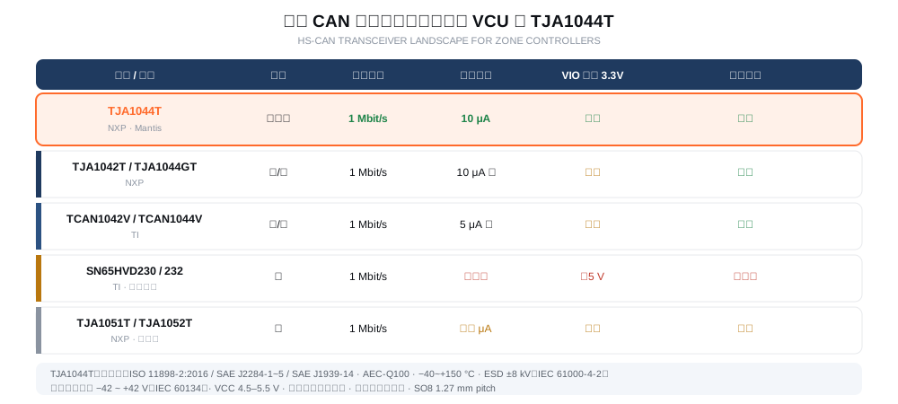
高速 CAN 收发器可选面不算宽,但差异都落在 VCU 关心的点上:通道数、待机电流、VIO 直连、总线唤醒。The high-speed CAN transceiver field isn't wide, but the differences land exactly where a VCU cares: channel count, standby current, VIO direct-connect and bus wake-up.

高速CAN 收发器选型对比与 TJA1044T 定位
型号Part 通道 / 速率Channels / rate 待机与唤醒Standby / wake 对 VCU 的取舍Trade-off for a VCU
TJA1044T
NXP MantisNXP Mantis
双通道 · 1 Mbit/sDual · 1 Mbit/s 10 μA 待机,本地 + 总线唤醒,VIO 直连 3.3 V10 µA standby, local + bus wake-up, VIO for 3.3 V MCUs 本方案选择。四路 CAN 两颗料搞定,VIO 省掉电平转换,待机与唤醒都满足整车需求,SO8 封装改版风险低。Our choice. Four channels with two parts, VIO removes the level shifter, standby and wake-up both fit vehicle needs, SO8 footprint keeps respin risk low.
TJA1042T / TJA1044GT
NXPNXP
单/ 双通道 · 1 Mbit/sSingle / dual · 1 Mbit/s 10 μA 级待机,支持总线唤醒,VIO 仅部分型号有10 µA-class standby, bus wake-up, VIO only on some variants 同门第性能接近。选它主要看具体型号是否带 VIO——不带 VIO 时接 3.3 V MCU 需要额外确认 I/O 容限(TJA1044C 就不能直接接 3.3 V)。Performance in the same family. The deciding factor is whether the specific variant has VIO — without it you must check I/O tolerance for a 3.3 V MCU (TJA1044C cannot connect directly to 3.3 V).
TCAN1042V / TCAN1044V
TITI
单 / 双通道 · 1 Mbit/sSingle / dual · 1 Mbit/s 5 μA 级待机更低,支持总线唤醒,VIO 部分型号Lower ~5 µA standby, bus wake-up, VIO on some variants 待机电流略优,适合对整车静电流极敏感的车型。若项目已有 TI 供应链或 CAN FD 规划,可优先评估。Slightly better standby current, useful where quiescent budget is tight. Worth evaluating first if TI is already in your supply chain or you plan CAN FD.
SN65HVD230 / 232
TI · 老平台常见TI · common in legacy designs
单通道 · 1 Mbit/sSingle · 1 Mbit/s 无待机模式,需 5 V MCU,无总线唤醒No standby mode, needs a 5 V MCU, no bus wake-up 老项目沿用没问题,但不适合新设计的 VCU:没有待机意味着整车休眠后这颗料仍在耗电,没有总线唤醒则必须额外做唤醒通路。四路需要四颗料。Fine for legacy projects, but not for a new VCU: no standby means this part keeps drawing current with the vehicle asleep, and no bus wake-up forces a separate wake path. Four channels need four parts.
TJA1051T / TJA1052T
NXP · 上一代NXP · previous generation
单通道 · 1 Mbit/sSingle · 1 Mbit/s 几十 μA 级,唤醒能力部分Tens of µA, partial wake capability 上一代方案,功耗与集成度都不如TJA1044T。新项目优先选Mantis 系列,除非供应链已锁定这一代。Previous generation, worse in both power and integration than TJA1044T. Prefer Mantis for new work unless your supply chain is locked to this generation.
Hardware Design

硬件设计要点:四路 CAN 怎么落地Hardware notes: bringing four CAN channels in

两颗 TJA1044T 撑起四路 CAN,BOM 是省了,但电气设计有几处不能省。Two TJA1044T parts cover four channels and the BOM shrinks, but several electrical details cannot be cut.

要点Topic 为什么Why 做法How
按域分配通道Allocate channels by domain 双通道不是随便凑一起。既然要分域,就让一颗专管高实时的一侧,另一颗专管容错的一侧,物理与逻辑都对应。Two channels shouldn't be paired arbitrarily. Since the network is segmented, let one part own the high-real-time side and the other the fault-tolerant side, matching both physics and logic. 建议 #1:动力 CAN(10–20 ms)+ 诊断 CAN(刷写/标定),都是500 kbps 且与安全相关;#2:车身 CAN(50–100 ms)+ 底盘 CAN。诊断与动力放一起,是因为诊断链路本身要求稳定且常需在动力域失效时仍能工作。Suggested: #1 powertrain CAN (10–20 ms) + diagnostic CAN (flashing/calibration), both 500 kbps and safety-related; #2 body CAN (50–100 ms) + chassis CAN. Diagnostics sits with powertrain because it must itself be robust and often needs to work when the powertrain domain is degraded.
总线终端电阻Bus termination CAN 是差分总线,两个120 Ω 终端电阻必须只在总线两端各放一个。中间节点重复放阻会造成阻抗失配,反射叠加,通信距离与速率都上不去。CAN is a differential bus: exactly one 120 Ω terminator at each physical end. Duplicating them at intermediate nodes causes impedance mismatch and stacked reflections, capping both distance and rate. VCU 作为网段中间节点通常不装终端电阻,由干节点位置决定;把整条总线的终端电阻集中放在最远的两个 ECU 上。分网后每路 CAN 独立计算终端位置。A VCU as a mid-bus node normally omits the terminator — place the bus's two terminators at the two farthest ECUs instead. After segmentation, compute termination separately per CAN channel.
共模电感(可选但强烈建议)Common-mode choke (optional, strongly advised) TJA1044T 即使没有共模电感也具备优异的 EMC 表现,这是它的一处优势;但 VCU 与动力总成同域,电机与充电机的噪声不容小觑。TJA1044T has excellent EMC even without a common-mode choke — one of its advantages — but a VCU shares its domain with the powertrain, where inverter and charger noise is significant. 按辐射发射测试结果决定:先不装,测;若骚扰超限再补共模电感。预留位置比一开始就焊死更灵活——加了电感会占板面积并影响信号完整性,留空可以后补。Decide from radiated emissions test results: fit it first, test, and add a choke only if noise exceeds limits. Reserve the footprint rather than committing — a choke costs board area and affects signal integrity, while an empty pad lets you add it later.
唤醒路径Wake-up path 整车休眠后要能被远程唤醒,同时要避免误唤醒导致静态电流异常上升。After the vehicle sleeps it must be remotely wakeable, without spurious wake events inflating quiescent current. 用 TJA1044T 的总线唤醒能力,配合 MCU 的唤醒中断;若需要"锁存某一路唤醒源",在 MCU 侧做唤醒源识别而不是硬件锁存,省一颗器件也省一路布线。Use the transceiver's bus wake-up together with the MCU's wake interrupt. If you need to latch which channel woke the vehicle, do source identification in the MCU rather than in hardware — one fewer part and one fewer net.
供电与 VIO 分开走Separate VCC and VIO rails VCC 供总线侧(5 V),VIO 供逻辑侧(3.3 V)。两者都要去耦,且各自就近放置电容。VCC feeds the bus side (5 V) and VIO the logic side (3.3 V). Both need decoupling with caps placed close to the pins. 两颗 TJA1044T 的 VCC 与 VIO 各自独立去耦,逻辑地与总线地在单点连接(通常是 MCU 下方),避免大电流回路穿过逻辑参考。Decouple VCC and VIO independently on both parts, and tie logic ground to bus ground at a single point (typically under the MCU) so high-current returns don't run through the logic reference.
故障注入与降级Fault injection and degradation CAN 有多种错误状态(总线关闭、错误被动、总线离地短路)。一颗收发器失效不应拖垮整车。CAN has many failure states (bus-off, error-passive, short to ground). One failed transceiver must not take down the vehicle. 利用 TJA1044T 断电时总线无源的特性:某域彻底掉电不会把总线拉死。软件侧配合错误计数与总线关闭恢复策略,网关在单域失效时继续转发其余域数据。Exploit the fact that TJA1044T is inactive on the bus when unpowered: a fully depowered domain won't drag the bus down. Pair it with error counters and bus-off recovery in software, and have the gateway keep forwarding other domains when one dies.
Gateway & Diagnostics

网关与诊断:VCU 的隐含职责Gateway and diagnostics: the VCU's implicit duties

这两块最容易被当成"顺带做的",但它们恰恰是 VCU 区别于普通 ECU 的地方。These two are easily treated as an afterthought, yet they're precisely what distinguishes a VCU from an ordinary ECU.

网关 · 信号映射Gateway · signal mapping

跨网转发不是复制报文。动力 CAN 上 BMS 报文的 SOC 是 0–100 整数,而仪表可能需要带小数的百分比,或需要同时转发 SOC 与 SOH。网关要按 DBC 数据库里的信号定义提取、转换、打包后发送。Cross-domain forwarding is not message copying. SOC on the powertrain CAN is an integer 0–100, while the cluster may want a decimal percentage, or may need SOC and SOH together. The gateway must extract, convert and repack per the DBC database signal definitions.

网关 · 周期改写Gateway · cycle rewriting

10 ms 的高速信号转到低速总线时改成 100 ms发送,减少车身总线负载。这需要在网关的路由表里为每条转发规则显式配置源周期与目标周期,而不是简单透传。A 10 ms fast signal may be sent at 100 ms on the slow bus to cut body-bus load. This requires the routing table to specify source and target cycles explicitly for each rule, rather than passing traffic through unchanged.

诊断 · OBD 与 UDSDiagnostics · OBD & UDS

诊断 CAN 接OBD-II 诊断口与各 ECU,负责排放相关故障码与状态读取(OBD)、以及统一诊断服务(UDS:请求当前条件、清除故障码、读写数据标识符)。VCU 自身也是被诊断对象,同时充当其他 ECU 的诊断报文路由。Diagnostic CAN links to the OBD-II port and the ECUs, handling emissions-related DTCs and status reads (OBD) plus Unified Diagnostic Services (UDS: request current conditions, clear DTC, read/write DID). The VCU is itself a diagnostic target and also routes diagnostic messages for other ECUs.

诊断 · 刷写与标定Diagnostics · flashing & calibration

OTA 升级与产线标定都走诊断通道。VCU 需要支持 bootloader 跳转到应用、以及失败回滚——这要求诊断 CAN 的连接在刷写期间保持可靠,且不影响其他域的正常运行。Both OTA updates and production-line calibration go through the diagnostic channel. The VCU needs bootloader-to-application switching plus rollback on failure — which means the diagnostic CAN link must stay reliable during flashing without disturbing normal operation of the other domains.

Checklist

设计检查清单Design checklist

从原理图到 EMC 测试,逐项确认。From schematic to EMC test, verify item by item.

检查项Item 通过标准Pass criteria
四路 CAN 速率与周期规划Rate and cycle plan for four channels 动力 500 kbps / 10–20 ms;诊断 500 kbps;车身 250 kbps / 50–100 ms;底盘 500 kbps。各路峰值总线负载率留 ≥30% 余量。Powertrain 500 kbps / 10–20 ms; diagnostic 500 kbps; body 250 kbps / 50–100 ms; chassis 500 kbps. Keep ≥30% headroom on peak bus load for each.
终端电阻位置Termination placement 每路 CAN 仅两端各一个 120 Ω,VCU 不重复安装;用万用表实测总线两端阻值应约 60 Ω(两个 120 Ω 并联)。One 120 Ω at each end of each channel, none duplicated at the VCU; measure at the bus ends — should read about 60 Ω (two 120 Ω in parallel).
VIO 与 VCC 去耦VIO / VCC decoupling 每颗收发器 VCC 与 VIO 各有就近去耦电容;实测逻辑侧纹波与总线侧纹波均在裕量内。Each transceiver has local decoupling on both VCC and VIO; measured ripple on logic and bus rails stays within budget.
单点接地Single-point grounding 逻辑地与总线地在 MCU 下方单点连接,回流路径不穿过逻辑参考区。Logic and bus ground join at one point under the MCU; return currents stay out of the logic reference area.
唤醒功能验证Wake-up verification 整车休眠后从每一路 CAN 分别唤醒均能成功;静电流处于目标预算内;误唤醒不会频繁发生。After sleep, wake-up succeeds from each CAN channel individually; quiescent current is within budget and spurious wakes don't occur frequently.
故障降级验证Fault degradation test 任一域彻底断电时,其余域通信正常;单域总线对地短路时网关继续转发其他域数据。With any one domain fully depowered, the others keep communicating; with one domain shorted to ground, the gateway keeps forwarding other domains.
EMC 测试EMC testing 辐射发射与传导发射满足目标法规(如 GB 34660 / CISPR 25、ISO 11452);抗扰度满足标准要求。Radiated and conducted emissions meet the target regulation (e.g. GB 34660 / CISPR 25, ISO 11452); immunity meets its standard.
温度测试Temperature testing 整机在 −40 ~ +125 °C(或按实车要求)范围内收发器与主控均正常工作,通信无丢帧。The unit works across −40 to +125 °C (or the vehicle's actual range) for both transceiver and MCU, with no dropped frames.
Let's talk

要做一台 VCU?Building a VCU?

告诉我们整车平台(乘用车 / 商用车)、CAN 路数与速率、各域节点数量、是否需要 CAN FD 与网关功能,我们按上文的框架帮你过一遍架构、器件选型与测试清单。TJA1044T 现货可配。Tell us the platform (passenger or commercial), how many CAN links and at what rate, node count per domain, and whether you need CAN FD and gateway functions — we'll walk the architecture, component selection and test checklist above with you. TJA1044T is available.