方案 · 关节组控制器Solution · Zonal Controller

关节组控制器Joint Zone Controller:双总线硬件方案: A Two-Bus Hardware Design

EtherCAT 上行,CAN 下行EtherCAT uplink, CAN downlink

一个区管 4~8 个关节,上接主控计算机、下接关节驱动器。本文给出这一层的完整硬件方案:总线怎么分、器件怎么选、位时序怎么配、哪些坑踩过就不要再踩。文中参数均为可落地的工程值,具体数值请以所选器件的原厂datasheet 为准。One zone covers 4–8 joints, linking the main computer above to the joint drives below. This is the complete hardware design for that layer: how to split the buses, how to pick parts, how to configure bit timing, and which traps to avoid. All figures here are engineering values; confirm against the selected vendor's datasheet.

Architecture

总体架构Overall architecture

两条总线各管一段,不是冗余也不是备份,而是按速率与成本分层。Two buses, each covering one segment — not redundancy or failover, but tiering by rate and cost.
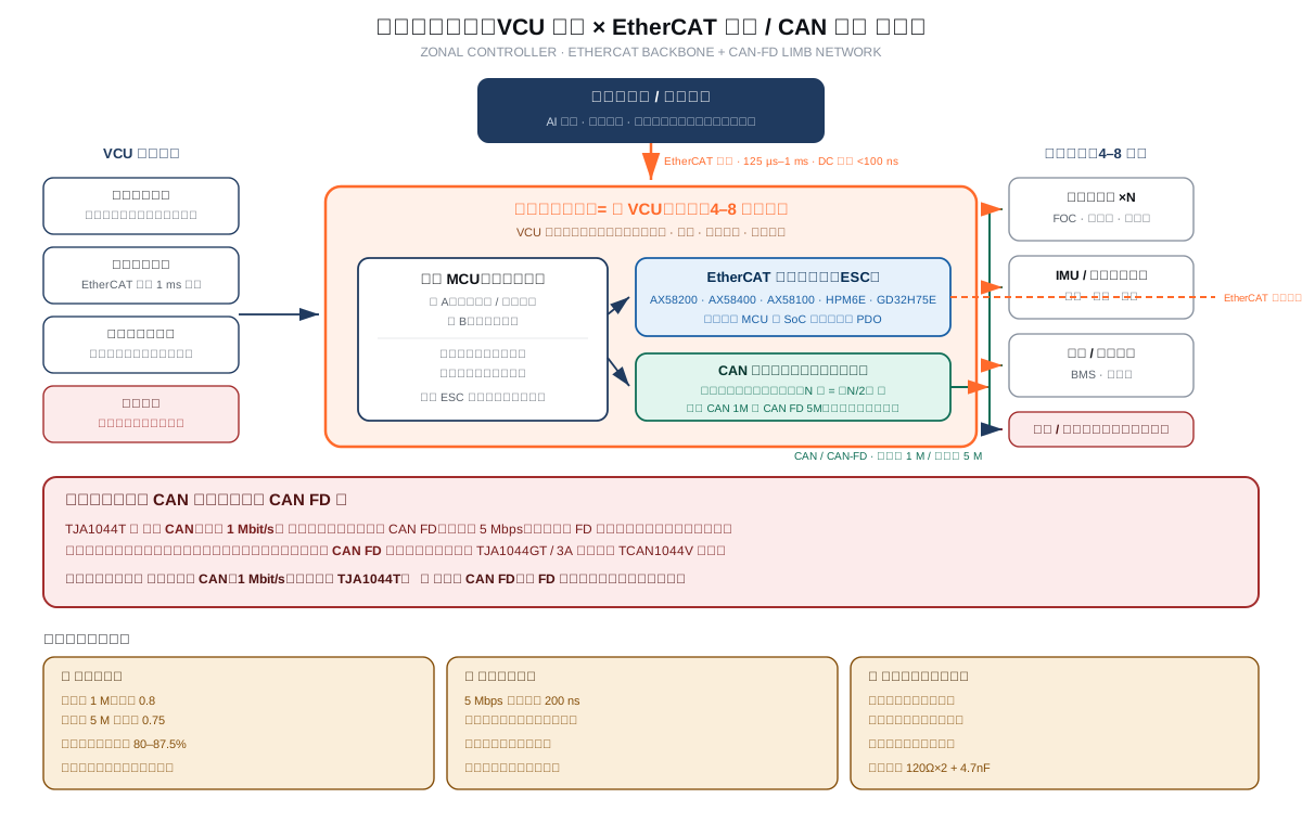
关节组控制器双总线架构框图

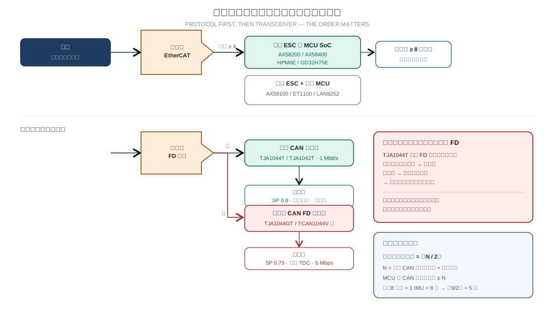
分层的理由很直接:EtherCAT 周期125 µs–1 ms、分布式时钟同步误差 <100 ns,代价是从站芯片与协议栈都不便宜;CAN 单节点成本低、抗电机干扰强,但速率只有 1 Mbit/s(经典)或数据段 5 Mbps(FD)。躯干与髋膝肩这类大关节要同步要带宽,用 EtherCAT;手指、手腕、颈部动作幅度小、实时性要求中等,用 CAN 完全够。结果是 40~60 DoF 的整机通常分6~8 个区,而不是把 40~60 个关节直接挂在一条总线上——每肢一区,既压低BOM,又把故障范围限制在一条肢体。The reasoning is straightforward: EtherCAT gives 125 µs–1 ms cycles with under 100 ns distributed-clock skew, but the slave chips and stack are not cheap. CAN is inexpensive per node and robust against motor noise, but tops out at 1 Mbit/s (classic) or a 5 Mbps data phase (FD). Torso, hips, knees and shoulders need bandwidth and synchronisation, so they get EtherCAT; fingers, wrists and necks have small travel and moderate timing needs, so CAN is sufficient. The practical result is that a 40–60 DoF machine is usually split into six to eight zones rather than hanging 40–60 joints on one bus — one zone per limb keeps BOM down and confines faults to a single limb.

先确认一件事:TJA1044T 不能跑 CAN FDFirst, one thing to confirm: TJA1044T cannot carry CAN FD TJA1044T 的物理层是经典 CAN,最高 1 Mbit/s。如果下行规划了 CAN FD(数据段 5 Mbps),这颗收发器收到 FD 帧的扩展控制位后会判定为协议违规,主动发出错误帧污染总线,结果是同一网段的节点全部掉线。
所以选型第一步不是比参数,而是先把下行协议定下来:
·走经典 CAN(1 Mbit/s)→ TJA1044T 可用,一颗管两路。
· 走 CAN FD(数据段 5 Mbps)→ 换成 FD 专用收发器(TJA1044GT / 3A 系列、TI TCAN1044V 等)。
另外两条硬规则:经典 CAN 控制器与 CAN FD 控制器不能混在同一网段;速率超过 2 Mbps 时必须启用收发器环路延迟补偿(TDC),否则控制器会把自己刚发出的位读回来,触发伪错误帧。
TJA1044T's physical layer is classic CAN, 1 Mbit/s maximum. If the downlink is planned as CAN FD with a 5 Mbps data phase, this transceiver sees the frame's extended control bits as a protocol violation and emits error frames that corrupt the bus — every node on the segment drops.
So the first selection step isn't comparing specs, it's settling the downlink protocol:
· Classic CAN at 1 Mbit/s → TJA1044T works, one part covers two channels.
· CAN FD with a 5 Mbps data phase → switch to an FD transceiver (TJA1044GT / 3A family, TI TCAN1044V).
Two more hard rules: classic CAN and CAN FD controllers cannot share a segment, and above 2 Mbps you must enable transceiver loop delay compensation (TDC), otherwise the controller reads back bits it just transmitted and raises spurious error frames.
Hardware

实物对照:板上装什么,壳体里装什么Hardware: what goes on the board, what goes in the housing

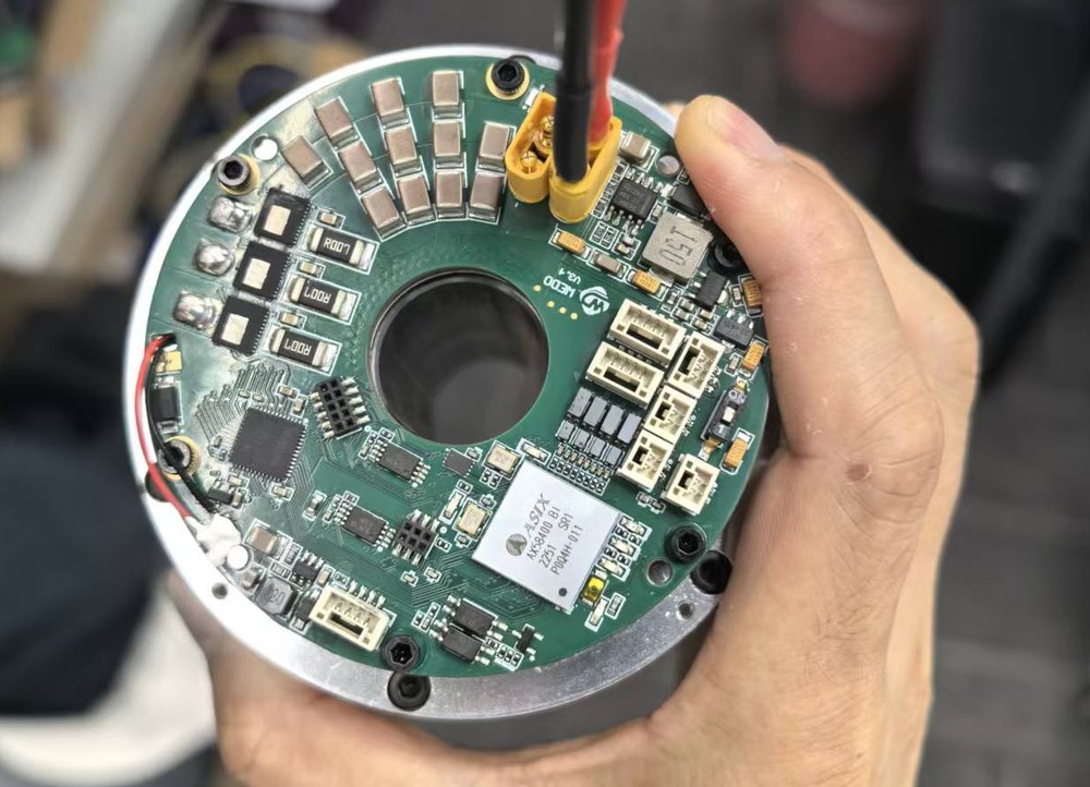
下面是一套关节模组的实拍:左边是驱动板,右边是铝合金壳体,两者对应上一节的框图。照片由用户提供,ReflowKit 仅作方案说明使用。Below are photographs of an actual joint module: the drive board on the left, the aluminium housing on the right, corresponding to the block diagram above. Photos are user-supplied; ReflowKit uses them for illustration only.

关节驱动板圆形PCB 实物
关节驱动板Joint drive board 圆板形态贴合关节壳体内径,中心孔给输出轴让位。外圈八颗功率管构成三相逆变桥臂;板上带 WiFi 模组与多路板间连接器,用于与组控制器通信。板上还会焊位置传感器芯片——电机端那颗对着转子,负载端那颗贴在减速器输出侧,这就是双编方案的硬件落点。The round board matches the joint housing bore, with the centre hole clearing the output shaft. Eight power devices around the edge form the three-phase inverter bridge; a WiFi module and several board-to-board connectors handle communication with the zone controller. Position-sensor ICs are also mounted here — one facing the rotor (motor side), one bonded to the gearbox output (load side). That is where the dual-encoding scheme lands in hardware.
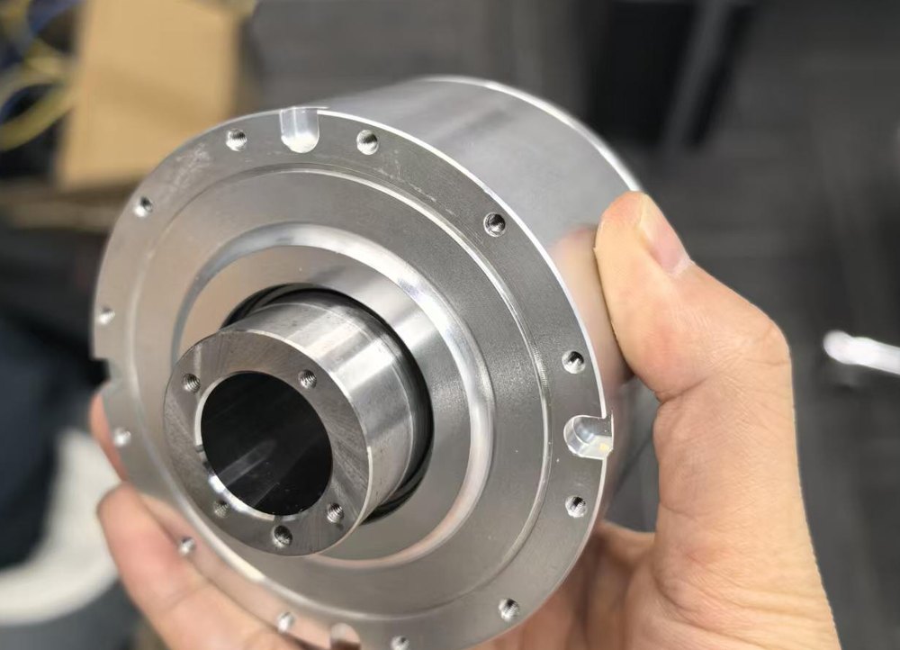
铝合金关节壳体与中空输出轴实物
关节壳体Joint housing 铝合金壳体沿圆周均布螺孔,用于压装驱动器与散热;中心的中空输出轴是电机转子穿出的地方,负载端编码器就装在这一侧测输出角度。壳体内部就是 CAN 与 CAN-FD 的走线空间——本节讨论的收发器、位时序与终端电阻,最终都要在这条几厘米的线束上跑通。Screw holes distributed around the aluminium bore take the drive pack and provide the thermal path; the hollow output shaft at the centre is where the rotor emerges, and the load-side encoder mounts on this side to measure output angle. Inside the housing is where the CAN and CAN-FD wiring lives — every transceiver, bit timing setting and terminator discussed here ultimately has to work across a few centimetres of harness.
Selection

选型:按这个顺序走Selection: follow this order

上行走 EtherCAT 还是别的,下行走经典 CAN 还是 FD,先定协议再选芯片。顺序反了会白打样。Settle uplink and downlink protocols before choosing any chip. Reversing the order wastes prototypes.

关节组控制器器件选型决策树
决策点Decision 判据Criteria 推荐Recommendation
下行协议Downlink protocol 单帧要装多少字节?上位机需要多高的遥测刷新率?线缆长度有没有超过 1 m?How many bytes per frame? What telemetry rate does the host need? Does any run exceed 1 m? 关节状态(位置 4 + 速度 4 + 电流 4 + 温度 2 + 状态字 2 = 16 字节)经典 CAN 要两帧,FD 一帧装完。若本体线缆普遍 <1 m 且需要 ≥50 Hz 遥测,选 FD;否则经典 CAN 够用且省事。Joint state (position 4 + velocity 4 + current 4 + temperature 2 + status 2 = 16 bytes) takes two frames on classic CAN but fits one frame on FD. If runs are generally under 1 m and you need ≥50 Hz telemetry, choose FD; otherwise classic CAN is sufficient and simpler.
上行器件Uplink device 关节数是否 ≥4?本区需要多少路数字 I/O?是否要省板面积?Four or more joints? How many digital I/O does the zone need? Is board area critical? 关节数 ≥4 或在意板面积 → 内置 ESC 的 MCU SoC(AX58200 / AX58400 / HPM6E / GD32H75E),一颗顶"ESC + MCU + PHY",BOM 降 20–35%。需要大量 I/O 且已有外部 MCU → AX58100(集成双 PHY + 32 路 IO + PWM/编码器/SPI Master,可不用外挂 MCU)。追求生态与文档 → ET1100。Four or more joints, or board area matters → an ESC-integrated MCU SoC (AX58200 / AX58400 / HPM6E / GD32H75E), replacing "ESC + MCU + PHY" and cutting BOM 20–35%. Many I/O with an existing host MCU → AX58100 (dual PHY + 32 I/O + PWM/encoder/SPI Master, works standalone). Ecosystem and documentation first → ET1100.
MCU 核数MCU cores 控制环周期要求多少?协议栈负载有多重?两者是否打架?What control-loop period is needed? How heavy is the stack? Do they contend? 关节 ≥8 → 双核:一个核跑实时控制与安全监控,另一个核跑 EtherCAT / CAN-FD 协议栈,核间用硬件信号量同步、共享片上 SRAM。单核在 4 关节以内没问题,关节一多就会互相拖累。详见从站芯片横比。Eight or more joints → dual core: one core for real-time control and safety, the other for the EtherCAT / CAN-FD stack, synchronised by hardware semaphores over shared on-chip SRAM. A single core is fine below four joints but becomes a bottleneck as joint count grows. See the slave chip comparison.
下行收发器Downlink transceiver 协议定了,路数定了,MCU 供电电压是 3.3 V 还是 5 V?Protocol and channel count settled; is the MCU on 3.3 V or 5 V? 经典 CAN + 3.3 V MCU → TJA1044T(VIO 引脚 2.91–5.5 V,可直连 3.3 V,省一级电平转换)。用量按 ⌈N/2⌉ 算,N 是本区总路数。同时确认 MCU 的 CAN 控制器通道数 ≥ N。Classic CAN with a 3.3 V MCU → TJA1044T (VIO pin 2.91–5.5 V attaches directly to 3.3 V, saving a level shifter). Quantity is ⌈N/2⌉ where N is the zone's total channels; confirm the MCU has at least N CAN controller channels.

关于双核,有一组可参考的实测数据:国民技术 N32H785 搭配中科院深圳先进院的关节一体化方案,M7 核跑 FOC 与三环控制、M4F 核跑 CAN FD 与 EtherCAT,实测 20 kHz 电流环、0→100 rpm 平均响应 106 ms、超调 4.43%、位置跟踪平均误差 0.54°。同类产品已在量产而非仅停留在参考设计。On dual core, a reference data point: Nationz's N32H785 with SIAT delivers a 20 kHz current loop with M7 handling FOC and three-loop control while M4F handles CAN FD and EtherCAT — measured 106 ms average 0–100 rpm response, 4.43% overshoot, 0.54° average position error. This class of part is in production, not just reference designs.

Transceiver

TJA1044T 用在一区里是什么位置Where TJA1044T sits in a zone

下面每项都注明"对关节组控制器意味着什么",方便直接对照设计。Each row notes what the parameter means for a zone controller, for direct comparison against your design.

Joint cabling flexes with every joint, so connector and harness stress far exceeds fixed installations — ±42 V and 8 kV ESD are production thresholds. Inactive bus when unpowered matters most here: one unpowered joint drive won't drag down the whole limb's bus, so the remaining joints keep communicating.
参数Parameter 值Value 设计含义Design implication
通道数Channels 双通道 一区 6 个关节 = 3 颗收发器。相比 6 颗单通道,BOM 与板面积大致减半。关节密集的机器人上板面积和重量是硬指标,这个收益直接落在结构件上。Six joints in a zone = three transceivers. Versus six discretes, BOM and board area roughly halve — and on joint-dense robots, area and mass feed straight into the mechanical budget.
速率Data rate 1 Mbit/s
(经典 CAN)(classic CAN)
决定了下行只能跑经典 CAN。若这一区需要 FD,换 TJA1044GT / 3A 系列或 TCAN1044V,不能沿用这颗。This caps the downlink at classic CAN. If the zone needs FD, switch to TJA1044GT / 3A or TCAN1044V — this part is not usable there.
待机 / 唤醒Standby / wake 10 μA 待机
本地 + 总线唤醒
机器人待机功耗直接影响续航。总线唤醒让上位机或工具能把休眠中的整机叫醒,不需要为唤醒单独拉一路常供电通路——这条在电池供电的移动机器人上很实用。Standby power maps directly to runtime. Bus wake-up lets a host or tool wake a sleeping machine without a dedicated always-on wake path — practical on battery-powered mobile robots.
VIO 引脚VIO pin 2.91–5.5 V 主控 MCU 一般 3.3 V 供电,总线侧要 5 V。VIO 让收发器直接挂 3.3 V 逻辑,省掉一级电平转换和一路电源噪声。注意:无 VIO 引脚的型号(如 TJA1044C)不能直接接 3.3 V MCU,选型时别只看功能。The host MCU is usually on 3.3 V while the bus side needs 5 V. VIO lets the transceiver sit directly on 3.3 V logic, removing a level shifter and a noise source. Note: parts without a VIO pin (such as TJA1044C) cannot attach to a 3.3 V MCU — check this before committing.
总线保护Bus protection ESD ±8 kV (IEC 61000-4-2)
总线引脚 −42 ~ +42 V
断电时总线无源
关节线缆跟着关节反复弯折,连接器和线束的机械应力比固定安装大得多,±42 V 耐压与 8 kV ESD 是量产门槛。断电时总线呈无源特性这点很重要:单个关节驱动器掉电不会把整条腿的总线拉死,其余关节照常通信。
温度 / 封装Temperature / package −40 ~ +150 °C (Tvj)
SO8,1.27 mm pitch
关节内靠近电机与减速器,温升明显,这一档温度裕量必须有。SO8 与常见单通道 CAN 收发器引脚兼容,从单通道迁到双通道时改版风险低。另有 AEC-Q100 认证,适合有车规背景的整机平台。Inside a joint, proximity to motor and gearbox means real temperature rise — this margin is required. The SO8 footprint is pin-compatible with common single-channel parts, so migrating single to dual channel carries low respin risk. AEC-Q100 qualification also suits platforms with automotive lineage.
标准符合性Standards ISO 11898-2:2016
SAE J2284-1 ~ -5
AEC-Q100
量产前不需要额外的协议一致性验证。若平台有商用车背景或出口需求,J2284 系列与 AEC-Q100 能省掉一轮认证沟通。No extra protocol conformance work before production. For platforms with commercial-vehicle or export requirements, the J2284 series and AEC-Q100 save a certification cycle.
Bit Timing

位时序:采样点配错,长帧必挂Bit timing: a wrong sample point kills long frames

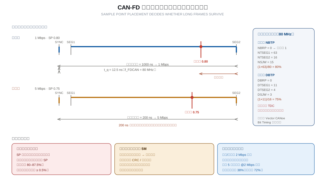
仲裁段与数据段速率独立配置,这是 FD 相对经典 CAN 的主要收益,也是配错的主要来源。Arbitration and data phases configure independently — FD's main benefit and its main configuration trap.

CAN-FD 仲裁段与数据段采样点配置图
One group at each physical end of the bus. The split structure provides 120 Ω differential termination while the capacitor gives common-mode noise a low-impedance path to ground. Expect about 60 Ω measured end to end, unpowered.5 Mbps is sensitive to impedance drift and contact resistance. Continuous flexing near an active joint drifts impedance, showing up as intermittent CRC or bit errors. Keep connectors out of the maximum bend angle — this matters more for reliability than the cable part number.
参数Parameter 取值Value 说明Notes
仲裁段波特率 / SP 1 Mbps / 0.8 决定节点数上限与通信距离。人体尺寸决定关节线束一般不超过 1 m,15 节点以内 1 Mbps 足够支撑 1 kHz 周期轮询。节点多、分布散时把 SP 统一提到 0.80–0.875,并确保全网节点时钟精度不低于 0.5%。Sets the node ceiling and reach. Human-scale joints keep runs under 1 m; below 15 nodes, 1 Mbps sustains 1 kHz cyclic polling. With many distributed nodes raise SP uniformly to 0.80–0.875 and hold node clock accuracy at 0.5% or better.
数据段波特率 / SP 5 Mbps / 0.75 1 米以内短线缆能稳定承受。位时间仅 200 ns,必须启用 TDC,否则控制器会读回自己刚发的位并判为位错误。Short runs under 1 m handle this comfortably. The bit time is only 200 ns — TDC is mandatory, or the controller reads back its own bits and reports bit errors.
终端 分裂终端 120 Ω × 2 + 4.7 nF 只在总线两个物理末端各放一组。分裂结构在提供 120 Ω 差模终端的同时,通过电容给共模噪声一条低阻抗对地通路,抑制共模辐射。断电实测两端之间应约 60 Ω。
拓扑 菊花链,禁止星型 星型或菱形在 2 Mbps 以上因阻抗不连续产生反射。实测数据:5 节点星型在 2 Mbps 下眼图水平张开度只有 38%,菊花链可达 72%。Star or diamond topologies reflect badly above 2 Mbps. Measured: a 5-node star at 2 Mbps gives only 38% horizontal eye opening, versus 72% for daisy chain.
线缆 耐弯折高柔线 5 Mbps 对特征阻抗漂移和连接器接触电阻很敏感。关节活动区的线缆长期弯折会导致阻抗漂移,表现为偶发 CRC 错误或位错误。连接器不要放在关节活动范围的最大折角处,这条对可靠性影响比换线缆型号还大。
错误处理 应用层监测 + 自动恢复 CAN 自带错误主动/被动状态机:错误计数超 127 进被动,超 255 进总线关闭。机器人振动与 EMI 引起的瞬时错误很常见,策略不当,一次干扰就把节点踢出总线。建议连续 N 次收到错误帧后主动休眠再上线,而不是一路重试到总线关闭。CAN has error-active/passive states: past 127 it goes passive, past 255 bus-off. Transient errors from vibration and EMI are routine on robots — a poor strategy lets one glitch kick a node off. Sleep briefly after N consecutive error frames rather than retrying into bus-off.
负载率 峰值留 ≥30% 余量 超过 60% 时低优先级帧的仲裁延迟显著上升。安全相关帧(故障报警、急停)应分配最高优先级 ID,低优先级遥测帧排在最后。Above 60%, arbitration delay for low-priority frames rises sharply. Give safety frames (fault, e-stop) the highest-priority IDs and put telemetry lowest.
Redundancy

关于冗余的三件事Three things about redundancy

要点Topic 问题The issue
冗余不是多并一根线Redundancy isn't a second wire 两路必须在物理路径、连接器、收发器、CAN 控制器四个层面独立。工程上可行的做法:左腿线束走左侧波纹管、右腿走右侧;腰部节点A/B 分别走上下两个出线口;连接器错位安装。把两路线缆并排绑在一起,一次机械磨损就会同时打断两条,冗余等于没做。冗余方案的收益要靠故障注入验证才算数:断开 A 路,确认能自动切到 B 路且整机不触发急停。The two links must be independent at four levels: physical path, connectors, transceivers and CAN controllers. A workable layout: left leg harness through the left conduit, right leg through the right, waist nodes taking A and B out through separate ports, connectors staggered. Tie them side by side and one abrasion disables both, making the redundancy worthless. Validate by fault injection: cut link A and confirm automatic switch to B without triggering an e-stop.
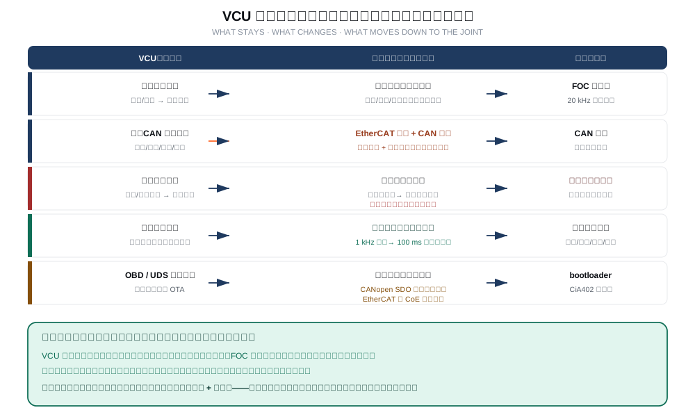
聚合不能掩盖失效Aggregation must not hide failure 组控制器把 8 个关节的状态聚合上报是合理的工程选择,但单点失效不能静默地把整条肢体从安全监控中移除。需要的机制:冗余唤醒路径、独立安全岛、旁路能力,或明确的降级运行模式。这些会多耗一点功耗,但保护的是必须保证的安全属性,不该省。Aggregating eight joints' state is a sound engineering choice, but a single failure must not silently remove an entire limb from safety supervision. You need redundant wake paths, independent safety islands, bypass capability, or an explicit degraded mode. These cost a little power — but they protect a required safety property and shouldn't be cut.
关节保护不能等上层Joint protection can't wait for the host 分布式关节可以接收协调指令,但不能依赖中央控制器做即时保护。关节驱动器要在硬件层检测过流、过温、编码器失效并自行切断功率级——上位机通信正常与否都不影响这一条。验证方法很直接:切断主控与组控制器之间的通信,关节仍应能独立断功率级。A distributed joint receives coordinated commands but must not depend on the central controller for immediate protection. The drive must detect overcurrent, overtemperature and encoder failure in hardware and cut its own power stage — regardless of host link state. Verification is straightforward: cut the link between main controller and zone; the joint must still trip independently.
Checklist

投板前检查清单Pre-production checklist

按顺序过一遍,每项都要有实测数据支撑。Work through in order; every item needs supporting measurements.

检查项Item 通过标准Pass criteria
下行协议与收发器匹配 经典 CAN → TJA1044T 可用;CAN FD → 必须是 FD 专用收发器,且全网段控制器均为 FD 能力。绝不可混用经典收发器与 FD 帧,也不可混用经典与 FD 控制器。Classic CAN → TJA1044T acceptable; CAN FD → an FD-specific transceiver is mandatory and every controller on the segment must be FD-capable. Never mix classic transceivers with FD frames, or classic and FD controllers.
位时序与采样点 仲裁段 1 Mbps / SP 0.8,数据段 5 Mbps / SP 0.75;节点多时仲裁段 SP 提至 0.80–0.875;全网节点时钟精度 ≥0.5%;启用 TDC。用 Vector CANoe 的 Bit Timing Calculator 交叉校验寄存器值。Arbitration 1 Mbps / SP 0.8, data 5 Mbps / SP 0.75; raise arbitration SP to 0.80–0.875 with many nodes; node clock accuracy ≥0.5%; TDC enabled. Cross-check register values with Vector CANoe's Bit Timing Calculator.
终端与拓扑 每段总线两端各一组分裂终端,断电实测约 60 Ω;禁止星型接法;支线长度 <0.3 m。One split terminator at each physical end, measuring about 60 Ω unpowered; no star topology; stubs under 0.3 m.
线缆与连接器 使用耐弯折高柔线;连接器避开关节活动范围最大折角处;做满行程弯折试验后重测误码率,与弯折前的基线对比。Flexible bend-rated cable; connectors away from the maximum bend angle; after a full-travel flex test, re-measure BER against the pre-test baseline.
收发器与 MCU 通道配比 双通道收发器数 = ⌈N/2⌉(N 为本区总路数);确认 MCU 的 CAN 控制器通道数 ≥ N;确认 MCU 供电电压与 VIO 范围匹配。Transceiver count = ⌈N/2⌉ where N is the zone's total channels; confirm the MCU has ≥ N CAN controller channels and that its supply voltage matches the VIO range.
总线负载率 峰值负载率留 ≥30% 余量;安全相关帧用最高优先级 ID;实测遥测周期与控制周期是否互相影响。Keep ≥30% headroom at peak; safety frames take the highest IDs; verify telemetry and control periods don't interfere.
单关节故障注入 逐个拔掉关节的 CAN 线、并单独令驱动器掉电:该关节应被识别为失效并切被动,其余关节正常运行,不得出现整组失能或整机急停。Unplug each joint's CAN link and power down each drive in turn: that joint must be flagged failed and go passive while the rest run normally — no group-wide blackout or full-machine e-stop.
本地保护独立性 切断主控与组控制器之间的通信,关节驱动器仍能独立检测过流/过温并自行断功率级。Cut the main-controller link: the joint drive must still independently detect overcurrent/overtemperature and cut its own power stage.
冗余验证(若做冗余) A/B 两路走不同线束路径、连接器错开、收发器独立;注入 A 路断线故障,确认自动切到 B 路且整机不触发急停。A and B through different harness paths, staggered connectors, independent transceivers; inject an A-link failure and confirm automatic switch to B without triggering an e-stop.
温升 整机满负载跑 1 小时以上,测收发器与主控外壳温升,确认留有裕量。关节内散热条件差,这一项常被忽略。Run at full load for over an hour, measure transceiver and MCU case temperature rise, confirm margin. Thermal conditions inside a joint are poor and this is often skipped.
Let's talk

说说你的关节组Tell us about your zone

告诉我们整机自由度、每区关节数、下行走经典 CAN 还是 CAN-FD、要不要冗余,我们帮你算器件用量、给位时序建议和测试清单。TJA1044T 现货可配。Send us the machine's DoF, joints per zone, whether the downlink is classic CAN or CAN FD, and whether you need redundancy. We'll size the components, propose bit timing and hand over a test checklist. TJA1044T is available.